Show Posts

This section allows you to view all posts made by this member. Note that you can only see posts made in areas you currently have access to.


Messages - Aidan

Pages: 1 2 [3] 4 5 ... 9
31
Park Flyers / Foamies / Re: Prop Size..
« on: January 18, 2011, 11:22:23 AM »
Quote from: "skyhawk newbie"
Just wondering.......


I'm useing a 8x4 folding Prop with 1750Kv Brushless Motor a 20a ESC and 1500mAh Li-Po's....

What I'm thinking of doing as I have 2 sets of 9x5 Folding Props (ordered by mistake)  was fitting the 9x5 to the above set up...

Will I burn the motor / ESC out  ?
if not , will I be able to fly longer ?? or just Faster


Thanks

 Sean
Hi Sean,

It's impossible to make a good guess as to whether this will cause you problems or give you better/worse performance without knowing a few more details.
i.e. What size is the motor? What are it's other specs and it's name? Is there any test data available from the manufacturer/distributor?
Also how many cells do you have in the 1500mAh pack. The voltage supplied to the ESC is one of the most important factors. I expect you're probably using either a 2s or 3s pack (2s = 2 cells in series, 3s = 3 cells in series) but it makes a big difference which.

There's 3 ways to know in advance how your power system is likely to perform:
1. Calculation using MotoCalc or similar software - can be very inaccurate but a good starting point if the manufacturer doesn't publish test data
2. Test data from manufacturer or other owners/testers - this is the best way to know what to expect before buying or doing your own tests
3. If there's no test data going, you can compare your motor to other similar motors (similar size stator and kV) that do have available data. This will only give you a very rough estimate. You could be a long way off.

If you don't have good data from the manufacturer and ideally even if you do, I suggest you purchase a current & voltage meter so you can see what your power system is actually doing. This is really the only way to know if you're pushing anything too hard (or not hard enough) and is essential if you need to do any trouble shooting.

The basic relationships for motor kV, prop size to electrical figures for a given power system are as follows:
Kv x supply voltage = theoretical RPM for no load (i.e. no prop)
The bigger the prop you put on a motor the lower the actual RPM will be.
As the difference between the theoretical no-load RPM and the actual RPM increases the current will also increase. So a bigger prop or a "draggier" prop will cause the current to rise. How much depends on lots of variables, some specific to the motor, some to the props, and the typical in-flight current will also depend on the airframe itself.
Lost power in the form of heat generated in the motor is down to power and efficiency. If the motor is, say, 75% efficient in an application where it's running at 16A on 7V then the electrical power input is 16x7 = 112W. Shaft power (what goes to the prop) is 112Wx0.75 = 84W and heat is 112W-84W=28W.
This 28W of heat will be made up of electrical losses from the resistance of the wires, etc and also mechanical losses due to bearings etc.

As you put more and more load on the motor the current will rise and in most of our applications the efficiency will drop. Both changes increase the heat generated. If the motor can't dissipate this heat quickly enough the motor temperature will rise high enough to damage the magnets or the burn/melt the wire insulation. That's how a motor usually dies.

...I seem to be rambling on a bit. Apologies I'll get back to the point now!

I'd guess a 9x5 prop of similar type to the 8x4 will probably cause a current increase of something between 20% and 40%.

more current = more power. If the batteries are well in spec then voltage won't drop much with the higher current and you'll get say 15% to 30% more power. The larger prop will be more efficient which will improve performance. Speed may not increase much unless the plane was originally very low on power because some of the extra pitch (5" instead of 4") will just compensate for the drop in RPM. However you should have significantly more thrust so steeper and faster climbs should be possible.
That's assuming you're still in the efficient operating range of the motor.

Aidan

32
How to... / How to set incidence pins in foamies
« on: January 14, 2011, 15:02:49 PM »
Fred can probably contribute more experience and tell you if this is necessary but I'd be inclined to insert a small balsa block or a disc of plywood into the fuselage and wing root and then fit the pin and socket to these rather than directly to the foam. This will spread the load and should make the pins far more secure and durable. You could also run the tube in the fuselage right through like the joiner tube for a little extra support if you wanted.

Aidan

33
Misceleanous / LiPo battery packs in parallel
« on: January 10, 2011, 11:52:06 AM »
Quote from: "Ron"
Thanks guys.  :clap:
Yes I guess it's a matter of keeping an eye on fully charged voltage per pack.

Was thinking I might try a Schottky Diode to separate the packs, like this one.

http://www.westfloridacomponents.com/mm5/graphics/ds2/40CPQ060.pdf

And it will handle both packs.
But even so, you're still talking 0.5v drop at 20 amps.

Ron

I don't think there's any need for the diode. It may even cause additional problems and is certainly introducing an extra potential point of failure.
The fact that the packs will equalise is not a bad thing! - you just need to ensure they do so safely which is as simple as checking the voltages before connecting them. The qualisation ensures that both packs are sharing the load and will maintain a similar charge state in use (providing they are similar type so that voltage sag under load is similar).

Aidan

34
Misceleanous / LiPo battery packs in parallel
« on: January 10, 2011, 10:34:31 AM »
Yep, What Dave said.

You can connect packs of the same series cell count in parallel but they should be close to the same charge state when you connect them as they will equalise and you don't want any high currents while that happens.

I've been charging my indoor lipo packs in parallel for a while now (Up to 20 at a time!) which works in the same way, just reversed. I make sure all packs are within about 0.2V before connecting them to the harness and leave the packs to equalise for a while before starting the charge. While checking the advisability of this method I did come across some figures for the sort of currents likely to occur when you connect packs of dissimilar voltage but I can't remember the figures and never measured it myself. I decided 0.2V was safe and went from there.

So, I'd suggest you check your packs are at similar voltage before connecting them to the harness and let them equalise for a short while after hook-up before use. Other than that you should have no problems. There's no reason you couldn't charge them in parallel too but you wouldn't be able to use the balancing function on your charger (if it has one) as it's the overall pack voltage and not the individual cells that will equalise voltage. If in doubt, charge separately.

Aidan

35
Indoor / Video
« on: January 05, 2011, 21:42:01 PM »
Here's the video.
This is from the start of our Monday session before we cracked out the streamers. Eanna's flying the purple-ish one, Stu in Red, Paul unpainted. These 3 are all the previous version which has a slightly more swept delta. I think the new one holds speed a little better when looping.
They will happily slow down to a crawl but it's mostly fast-ish flying in this video. They're a little noisy because of the slot but not as loud as the camera makes them seem.

No video of some of the more lively stuff later in the session - I was too busy flying!
[youtube]http://www.vimeo.com/moogaloop.swf?clip_id=18470882[/youtube]

36
Indoor / The Imp - EPP Indoor Combat Plane
« on: January 05, 2011, 20:52:44 PM »
No, it's definitely an Imp.

Sumo - Pah! :wink:

The video is still processing on Vimeo. Hopefully I'll be able to post it shortly.


Aidan

37
Indoor / Pictures
« on: January 05, 2011, 19:17:24 PM »
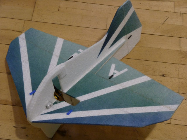
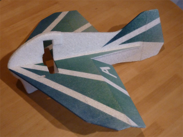
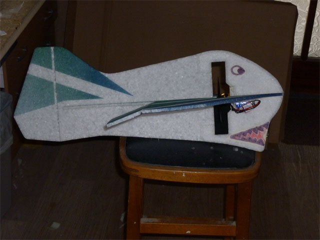
All finished: AUW is 130g


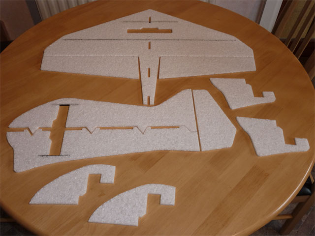
All the bits cut out and the 4 pieces of carbon glued in place


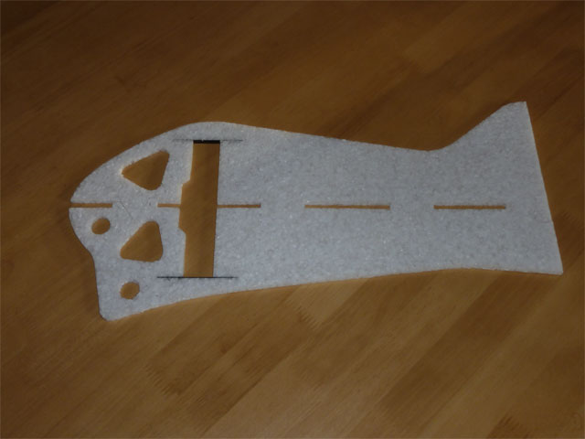
Cut outs in nose centre lamination. This isn't intended for weight saving. The idea is  idea is to add some flexibility and bounce to the nose. Hard to tell but I think it works. It does no harm either way.


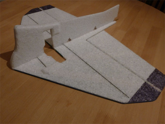
Assembled inverted using Uhu Por


Top half and rudder added. Ready for the radio gear and power system. The hinges are done with Uhu Por - easy, tidy and strong.


The "chin" is designed for skidding take-offs but it's also the perfect shape for a toothy paint job! Especially suitable if it's called the Imp


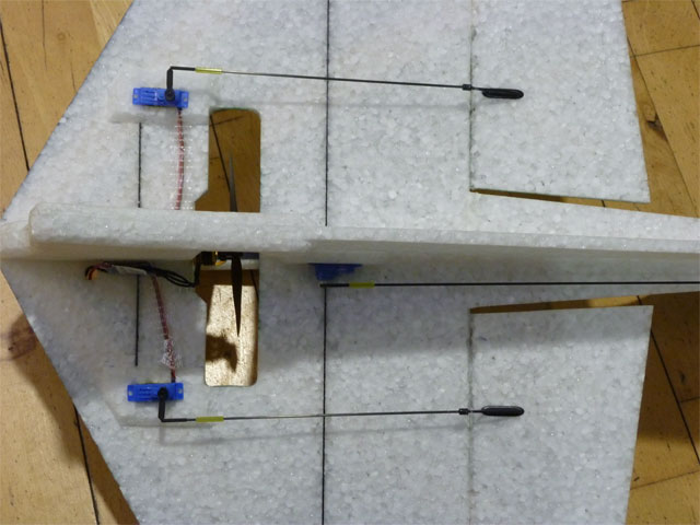
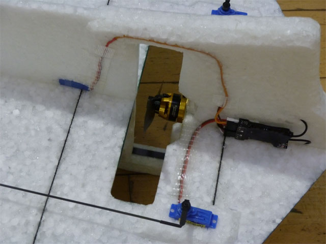
Radio installation is easy. We glued the servos flat to the foam on the early ones but they were a little vulnerable to getting knocked loose. Now I'm putting a 2nd layer of EPP where the servos go and cutting a slightly undersize hole. Push fit servos! No need for pushrod guides if you use 1.5mm carbon rods. I used 1.2mm rods with supports on earlier versions.


The only slightly inconvenient part of the build is that you may need to extend your rudder servo lead. It only takes a few minutes though.


Video to come!

Aidan

38
Indoor / The Imp - EPP Indoor Combat Plane
« on: January 05, 2011, 16:38:57 PM »
If you were at the CMAC Indoor fly-in at Middleton last October you might have seen the little orange EPP delta I was flying. I designed it with indoor combat, pylon racing and general messing about in mind. It flew well but needed some tweaking to make it as crash-proof and practical as I wanted.

I got time to sort it out and do some testing over Christmas and now it's working very well. I think I'll call it the Imp but any better suggestions will be gratefully considered :?: !
We had 4 of them in the air together on Monday for some combat (with and without streamers) and we're all agreed it's great fun! Lots of collisions, lots of streamer cuts, lots of fun and no significant damage (nicks from enemy props is about all we've seen).

It's built entirely from 6mm EPP (grade 20L – this is the soft stuff) and a little 3x0.5mm carbon strip. The prop's in the middle and it's got a big, blunt, bouncy nose.
It's virtually immune to head on collisions with walls, floors and roof beams (we've tested this several times now!). There's no landing gear or other breakable bits sticking out (but it can still take off easily from a smooth floor due to the new fuselage shape).

I'll post some photos in a couple of hours and maybe some video if I have anything suitable on the camera. I lost the CAD file for the latest version  :!:  so I'll need to re-draw it before producing a plan and then I'll post it here.

Technical specs, photos and plans coming soon!

Aidan


P.S.
This is my excuse for not making progress on the Index 4......

39
Slope Soaring / Happy new year!!
« on: January 04, 2011, 11:02:43 AM »
Happy new year guys!

40
Radios / Jeti radios... It's official!
« on: December 08, 2010, 14:29:06 PM »
Stop being negative.

JETI are going to build their radios to order and provide a vast range of user interfaces (all 100% glitch free). They will also provide a myriad of tranmitter designs. These will be available in any number of materials, shapes and colours with your choice of gimbals, sticks, switches, displays, digital or mechanical trims. You will even be able to e-mail JETI photographs of your hands and a video of your hands while flying and they will build an ergonomically optimised configuration just for you.
You can choose NiMH cells or ask for lipo, solar or wind power.
Standard USB or WiFi connectivity can be used for programming, making back-ups and simulator flying via your PC or laptop.
Virtually no limit on number of model memories or flight phases.
The optional voice or telepathic activation for trims and switches allows you keep your hands on the sticks at those critical moments or you can hand over to the transmitter to fly your plane to safety using the built in telemetry, radar and vision systems.

It will cost approx €10
...maybe €12 if you go for the fancy options.

Aidan

41
Radios / Jeti radios... It's official!
« on: December 08, 2010, 13:16:01 PM »
Excellent!

I hung around a while before going 2.4 in the hope they'd do this sooner but switched with a JETI converted Multiplex EVO earlier this year. Still it'll be good to see what they come up with. Hopefully they'll have sensible & flexible programming (something similar to Multiplex?) in which case I just might be interested next time around.

Aidan

42
Slope Soaring / DS BIRD
« on: December 07, 2010, 17:07:04 PM »
I like that!

Definitely worth considering. It would be a nice change to build a wood plane again - it's been a while.
I'll have to see if I can afford it after the budget today.

When do think you'll you have them in?

Aidan

43
How to... / Arming an ESC
« on: November 19, 2010, 11:44:41 AM »
Quote from: "Richard Boyd"
For my servo travel I tend to use 150%
That is just me !
I would rather have the full resolution of the servo and set the control horns and servo arms to reduce travel or increase it.

Richard

If I'm building a duplicate plane I go for the full range of movement but if it's something new I allow some flexibility and so far I've never bothered re-making the linkages after fine tuning the deflections. Changes are usually small. My new indoor delta would be an exception - the original rudder design was ridiculously powerful and servo travel had to be chopped to about 50% or 60% of the original settings to keep it sane! You're losing a lot of resolution and centring accuracy by doing that but it's not exactly a precision plane so it's not a big deal. If it was for F3P I'd be more concerned.

Which radio are you using that uses 150% as 100%? Is that Spektrum?

Aidan

44
How to... / Arming an ESC
« on: November 19, 2010, 08:38:39 AM »
Wow - Different figures for different channels! That's a whole new level of silliness. I presume they've done that because they reckon you'll need plenty room for adjustment and trimming on the primary controls but not so much on the auxillaries. It seems like excessive "user friendliness" to me. Try making something too user friendly and you just make it into a confusing mess that tries to tell you what to do and is bad at doing what you want.

I typically try and set up planes on my EVO so I have the deflections I expect will be about right at around 80% to 85% servo travel. Any less and you're compromising a lot on servo torque and resolution. Any more and you don't have much flexibility. Seems like that would correspond to around 115% as a starting point on Futaba.

Aidan

45
How to... / Arming an ESC
« on: November 18, 2010, 23:38:51 PM »
There is a standard but it's based on the signal frequency not the movement of the servo. There's a standard centre position which I think all radio brands use (including Multiplex in UNI mode. In MPX mode there's a 9% difference) Different servos may have different max deflections bu the signal range that produces them should be pretty much standard. So full travel on one servo will happen with the same signal input as produces full travel on any another servo. The % thing is just a convention. As far as I'm concerned 100% servo travel is the full range of motion available. However JR, Futaba and probably most radio brands don't treat it that way. They take, say, +/-80% of the actual available servo travel and call that +/-"100%" on their tranmitters. This means if you set up your plane using "100%" throws and then decide you need more you can have another 25% because you weren't really using 100% to start with. As I mentioned earlier , I believe multiplex mean it when they say 100%. If I remember correctly anything over 100% on a Multiplex radio only has an effect if it's feeding into a mixer or is the result of a trim adjustment and it's shifting the relationship to the stick position but not increasing the available throw.....I might be wrong about that last bit!
I recently got a JETIbox and have started using it to set servo centres and check available deflections - very convenient when setting up a model. It allows you control the actual signal value throughout the full range. I can take a look tomorrow evening and see what the actual range is and where the centrepoint lies. I think the standard is 1500ms with a range of +/-500ms but I'm not sure. It might be 1600ms.

Pages: 1 2 [3] 4 5 ... 9