Just in case anyone is tempted to build a new model for the forthcoming season, and as it’s pi**ing down with rain outside so I can’t fly mine, I thought I’d share my experiences of modifying the ubiquitous “Phase 6.”
I’m not an expert on this, (or any other subject) but I have been flying (and crashing) Phase 6’s regularly of the past three years and, therefore, have gained some fair amount of knowledge as to their strengths and weaknesses.
Of course, as with most changes from original designs, there can be disadvantages as well as advantages. In my personal view these modifications serve as overall improvements in the planes structure and performance.
Most of these modifications are best, and indeed some of them can only be done, while building the plane from scratch. Modifying an existing plane could prove rather tricky.
1/ The most important alteration from the original instructions is NOT to use a single, central, aileron servo. The problem surrounds the fact that such a servo, fitted into the underside of the wing, means that part of the servo will protrude down into the saddle area of the fuse. This fact is not a problem in itself until the pilot has one of those awkward landings when one wing tip touches Terra Firma before the rest of the airframe. The retaining wing plate will snap (as it’s supposed to,) allowing the wing to rotate and separate from the fuse. The result is that the servo forces the insides of the fuse apart,…….breaking the fuse at the wing saddle area. Just what you don’t want!
The solution therefore, is to fit two smaller servos into the underside of the wing, in front of each aileron. Not difficult to do as I shall now explain.
It’s simply a question of marking out where you want the servo to be in the wing. I tend to place it in the thickest part of the wing. Mark out the position and cut an appropriately sized hole. The styrene core of the wing is easy to remove.
This entry is an addendum to the above. I now understand that Chris Foss no longer produce Phase 6’s that use a single central aileron servo. The production of the wing has been modified and now comes with two recess’s cut into the underside of each wing half to facilitate wing mounted aileron servos.(Addendum added 27th December 2012) The only slight problem is making a hole through the core along the length of the wing for the servo cable to go through.
This is best done while the wing is still in two halves. (Before being glued together as per instructions.) I use a piece of steel rod. Heat one end up until drops of water (or spit) ‘bounce’ off of it and then insert the hot end into the styrene core from the root end of the wing half.
Now, at this point the question becomes, “How do you know whether the rod will emerge at the hole you made for the servo?”
To solve this problem I rely on the old adage that I learnt while riding motorcycles. “You will go where you are looking, so look at where you want to go.” (i.e. at the road ahead, not at your reflection while passing a big shop window.)
This translates to looking at the servo hole while pushing the rod through the wing core.
Well, it works for me! I’ve never missed the hole yet. (Famous last words.)
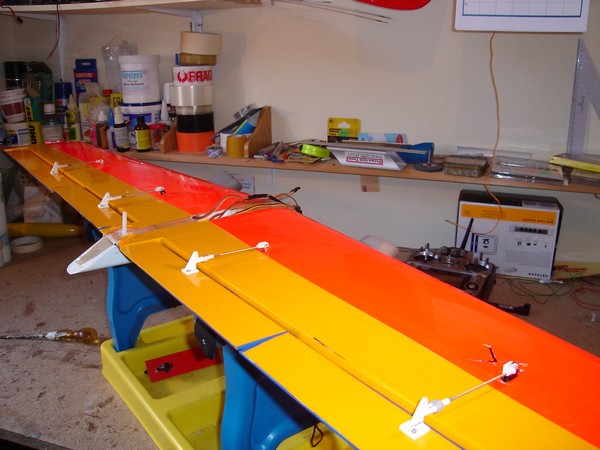
While we are on the subject of putting servos into wings, I would advise anyone performing these modifications to seriously consider making a ‘Full House,’ or ‘Quad’ wing.
By fitting ailerons and flaps you will greatly increase the performance envelope of your Phase 6. Especially if your Tx has Flap-to-Aileron mixing availability. By using the flaps as ailerons you produce a very large aileron control surface which will enable to plane to perform spectacular roll rates. In addition, the benefit of ’Crow Braking’ makes landing easier, and if flying in light lift conditions, dropping those flaps one or two millimetres increases the lift generated by the wings.
I think 4 servo wings are a definite ‘No Loose’ situation. (Well, just a very small % of extra weight.)
2/ Now,…. I want to have a quick word with you about flying in very windy conditions.
One of the big problems I’ve found with the standard set up of the Phase 6 was it’s reluctance to penetrate into strong winds. I knew that if I added ballast that would probably improve the models penetration but the problem was WHERE to but the lead weight?
The planes’ CoG is around 4½ inches back from the L.E. at the wing root. The problem, I found, was that at that point there is no room in the fuse because of, a) the wooden elevator push rod, b) the wires for the Pull - Pull rudder control, and c) that central aileron servo. (If it has been fitted, per the standard building instructions.)
Replacing the wooden push rod and rudder cables with plastic snake push rods allows the snakes to be secured to the sides of the fuse thereby enabling the area around the CoG to be used for ballast.
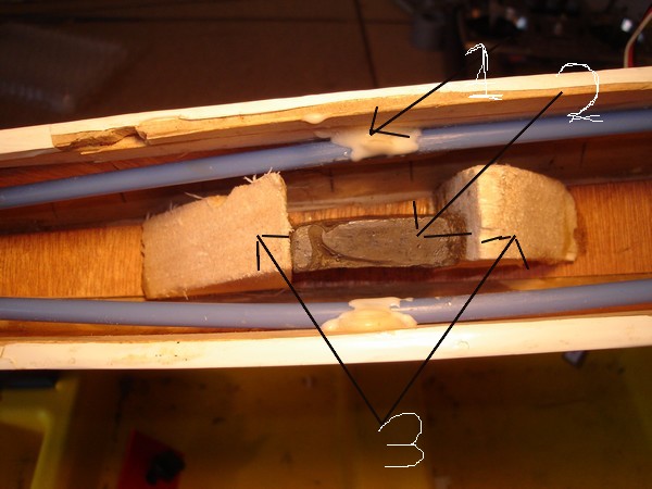
I simply cut a square piece of balsa block 45mm x 45mm diagonally and stuck them to the floor of the fuse 30mm apart. (Marked as ’3’ in the following picture) That serves as a securing point for the lead ballast blocks. (Marked as ’2’ in picture) These I made out of Fishing weights, (by far the cheapest way of buying lead that I’ve found. €1.50 for 500grms of lead) and then cut the fishing weights to the individual weight I wanted and simply hammered them into a square shape so they fitted between the balsa retaining blocks . I made mine so that when fully ballasted three such lead squares would fit, side by side, across the width of the fuse. To stop them rattling around when using less than three ballast weights, I squash some bubble wrap down the sides, and also across the top of the weights to stop them hitting the underside on the wing during aerobatic manoeuvres. (Marked as ‘1’ in picture#3 are the blue snake control rods glued to the sides of the fuse.)
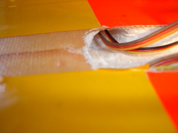
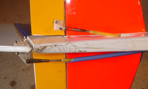
Of course, using snakes instead of the original wooden rod and pull - pull cables does mean some further mods’ are needed. Namely securing the snakes (to stop them from flexing) as they travel down the inside of the fuse, and bringing them out of the sides of the fuse just before the tail of the plane, and securing them to the appropriate control surface. SEE PICTURE #4. Sorted!
3/ Here’s a simple modification that I’ve found causes a respectable improvement in flight speed.
The building instructions tell you to shape the wing leading edge to a “D” profile. I suggest making the L.E. into a sharper “>“ type profile. There,….nice and simple.
What‘s next?………….
To Be Continued................