Seems every time I go flying people ask me about this tray. I'm regularly asked where I got it, to which I always reply 'I found it in my workshop'.
I've been pointing folk to this thread, so I thought I'd better add some more photos of the finished product, so that construction is as self explanatory as possible.
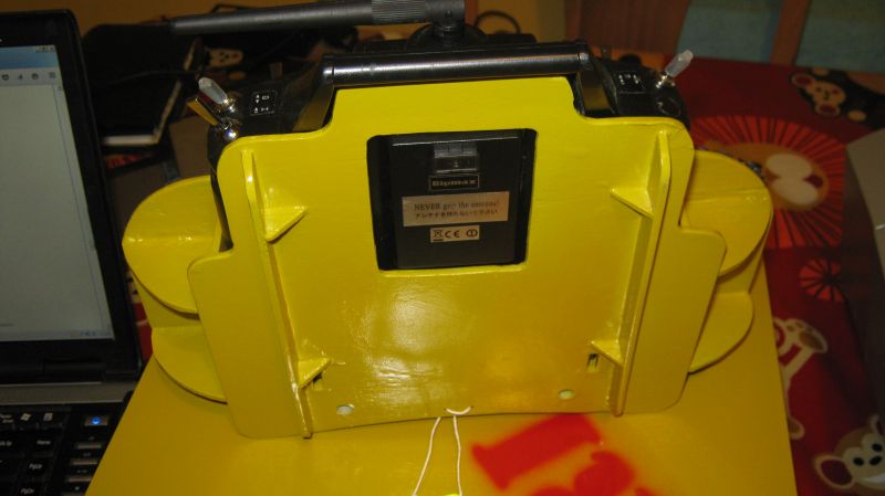
Underside showing runners: I had some scrap lengths of ply so I just rounded the ends and used some more scraps to make triangular gussets to keep everything off the ground. The RF module is clearly visible, sitting snugly in it's cutout, as are the two slots for the battery compartment 'feet'
To make everything solid the tubes I use to locate the harness rods are glued into the top and bottom plates. I think this shot gives a really good idea of how the whole thing was assembled.
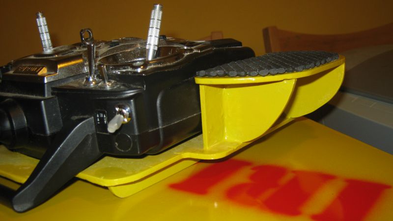
Front quarter, showing curved backplate and front gusset. Neoprene rubber hand 'grips' clearly visible here Not sure if I said already, but placed whilst final clear coat is still wet.
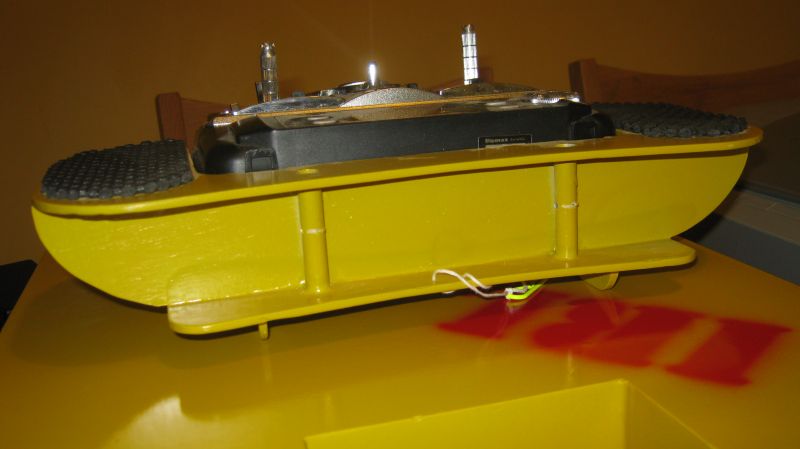
View from the back. Shows backplate and alu tubes that the harness rods slide in to. The string is tied to the two clips I use to hold the harness rods in place - so that I don't lose them when the tranny is not in use.
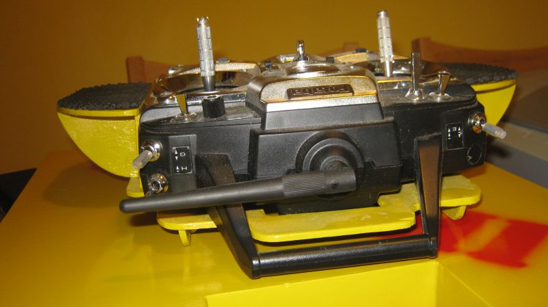
Front view, showing how the integrated tranny handle fits over the bottom front of the tray. Shows front gussets for supporting sides/base from tray top.
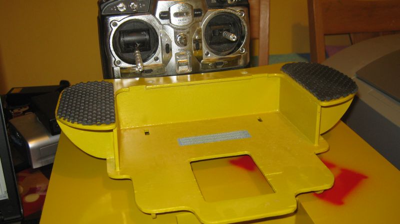
The magic velcro that holds the tranny in place. Not a a lot of velcro, but enough to hold the tranny in place when the tray is turned upside down.
Shows the overall shape of the bottom and cutouts for RF module and the feet on the battery compartment lid.
I can't recommend enough making a mockup out of cardboard before cutting timber (or whatever your preferred material is). This guarantees a good fit of the transmitter to the tray.
Since I'm lazy, the joint areas are large, and the transmitter is light, cyano (mitrebond) was used everywhere. A couple of engineers squares come in handy to keep everything aligned whilst the cyano kicks.